Introduction
In the first part of the basic ISE configuration series I guided you through the appliance installation process. In this one I will show you how to add a switch. On configured ports the switch will then send authentication requests to ISE. Ports can also be excluded from ISE authentication to use existing port configurations.
Please keep in mind that I will only go through very basic configuration options to make ISE work in your lab environment. This guide might not include advanced configuration options.
Supported Switches
For this demonstration I will be using a Cisco Catalyst 1000 Switch. If you are using a different switch model you can look up the spec sheet of your switch model to find out if it supports ISE. A different model may require other commands and/or steps to work properly.
Prepare your Switch
As mentioned before I will use my Catalyst 1000. Even though the steps are similar on other switches the commands you need to use might be different. My switch currently has only a very basic configuration. Including a couple VLANs, trunk and access ports.
Connect to your switch and into configuration mode:
enable
configure terminal
Enable AAA Functions
Until you use the aaa new-model command all other AAA-Commands are hidden!
Enable AAA functions:
aaa new-model
Create an 802.1X port-based authentication method list:
aaa authentication dot1x default group radius
Required for VLAN/ACL assignment:
aaa authorization network default group radius
Authentication and authorization for webauth transactions:
aaa authorization auth-proxy default group radius
Enables accounting for 802.1X and MAB authentications:
aaa accounting dot1x default start-stop group radius
Uses a single session ID for a client no matter which authentication method is used:
aaa session-id common
Update AAA accounting information periodically every 5 minutes:
aaa accounting update periodic 5
Receive the session termination messages after the switch reboots:
aaa accounting system default start-stop group radius
Enables ISE to act as a AAA server when interacting with the client. Use your ISE installations primary IP address.
In this example my ISE IP is 10.10.10.150 and the key is isecold:
aaa server radius dynamic-author
client 10.10.10.150 server-key 0 isecold
RADIUS Server Configuration
Configure the switch to interoperate with Cisco ISE acting as the RADIUS source server.
Include RADIUS attribute 8 in every Access-Request:
radius-server attribute 8 include-in-access-req
Include RADIUS attribute 25 in every Access-Request:
radius-server attribute 25 access-request include
Wait 3 x 30 seconds before marking RADIUS server as dead:
radius-server dead-criteria time 30 tries 3
Enable RADIUS server. I named it ise in this example. You can name your RADIUS server however you like:
radius server ise
Use RFC-standard ports (1812/1813) and set your key. In this example my ISE IP address is 10.10.10.150 and the key is isecold:
address ipv4 10.10.10.150 auth-port 1812 acct-port 1813
key isecold
Send RADIUS requests from the Management VLAN. In my case it’s VLAN99. The VLAN needs an IP address assigned. The IP will later be used to add the switch to our ISE appliance:
ip radius source-interface vlan99
Configure your ISE Appliance
You should already have a running ISE appliance at this point. Otherwise, take a look my previous guide: Install Cisco ISE in your Homelab Environment.
Add your Switch
Connect to ISE via WebGUI using its primary IP address and HTTPS. Login with the credentials you defined in the installation process.
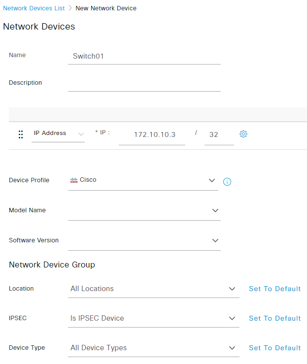
To add a new switch navigate to Administration -> Network Resources -> Network Devices and select Add.
Give your switch a name and enter its management IP in the IP Address field:
Check RADIUS Authentication Settings and enter your Shared Secret that we defined previously:
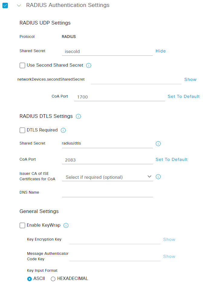
That’s already it for the ISE configuration part. You can leave all other settings to default for now.
Validate Connectivity
Let’s validate the connectivity to ISE. Login on your switch again and run the following command to display the log:
show logging
You should see an entry similar to the following one:
*Jul 12 2022 21:19:29: %RADIUS-4-RADIUS_ALIVE: RADIUS server 10.10.10.150:1812,1813 is being marked alive.
If you can’t find the entry above, reload your switch and view the logs again:
reload
Configure Switch Ports
After the global switch config is done we need to set up the switch ports to use ISE. Since I have already connected a couple of devices to my switch I will only use port 1 to 4.
Select the interfaces you want to configure:
interface range gi1/0/1-4
First you should set a black hole VLAN. This VLAN should not be configured on your trunk ports nor should clients on this VLAN have access to your network. An alternative would be to set your access VLAN but keep in mind that all connected clients have access to this VLAN without authentication. Depending on your switch location or use case you could also set a guest VLAN as the default.
Set you switch in access mode and configure your VLAN. I will use VLAN 999:
switchport mode access
switchport access vlan 999
Open-mode allows traffic to be bridged onto the data and voice VLANs before authentication is completed. Cisco strongly recommends using a port-based ACL in a production environment to prevent unauthorized access!
Enable open-mode authentication:
authentication open
Apply a port-based ACL to determine which traffic should be bridged by default from unauthenticated endpoints onto the access VLAN. Since you should allow all access first and enforce policy later, you should apply ACL-ALLOW to permit all traffic through the switch port:
ip access-group ACL-ALLOW in
Enable port-based authentication on the interface:
authentication port-control auto
authentication violation restrict
Enable MAC Authentication Bypass (MAB):
mab
Enable 802.1X on the switchport:
dot1x pae authenticator
Set the retransmit period to 10 seconds:
dot1x timeout tx-period 10
Check Port Configuration
After the ports are configured you can do another test. Connect a client to one of your ports and in the logs you should see a failed authentication entry for your client:
show logging
The entry should look similar to the following one:
Jul 12 2022 22:30:11: %MAB-5-FAIL: Authentication failed for client (ffff.ffff.ffff) on Interface Gi1/0/4 AuditSessionID C0A863030000000E004CEEA0
Conclusion
The basic configuration is now done, good job! Every device connected to your configured switch needs to authenticate to ISE first. You can now keep track of what’s happening on your network and implement advanced security checks for your access ports. In the next post I will show you how to create your first policy to assign VLANs dynamically using ISE.